Hi,
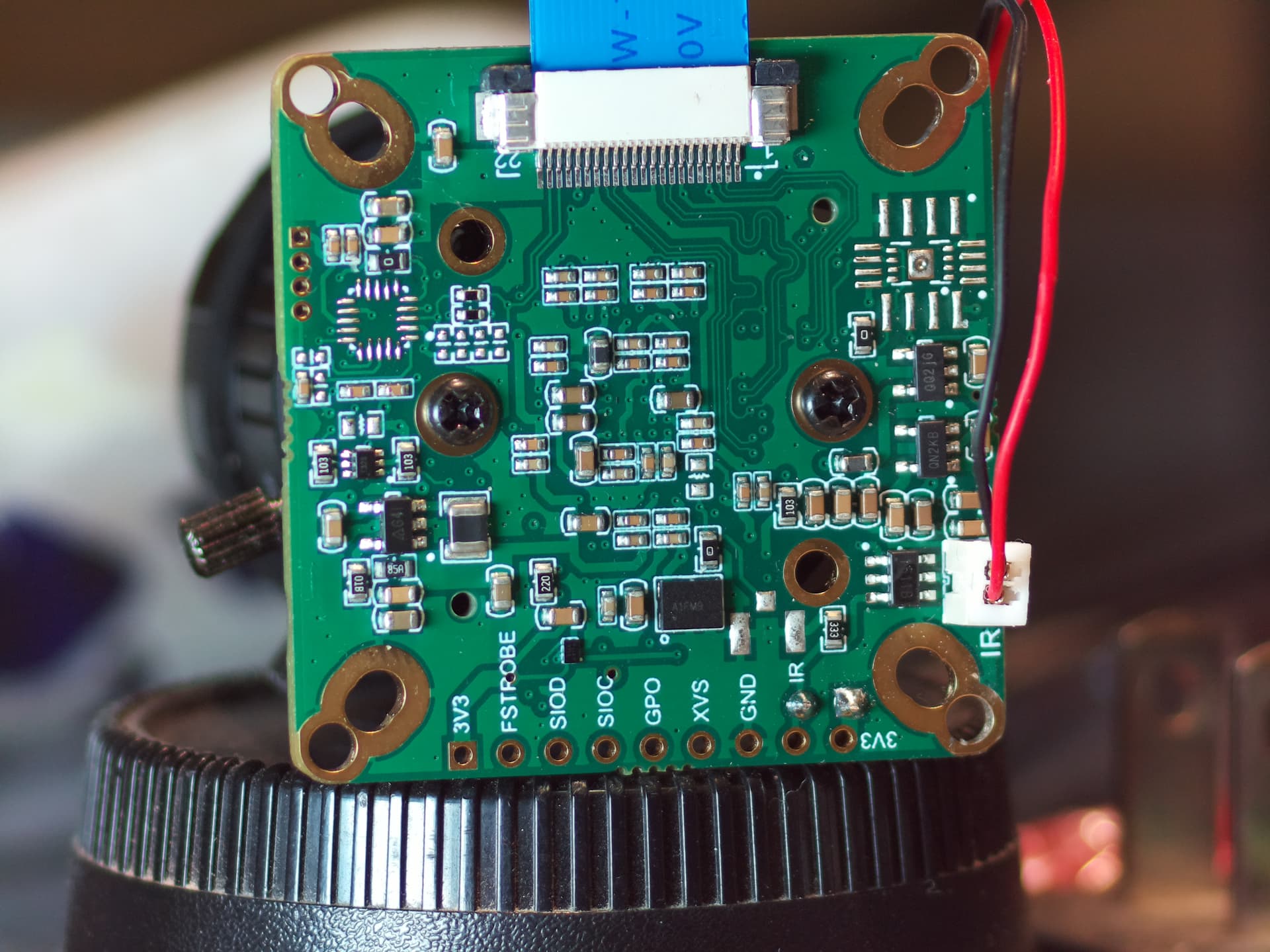
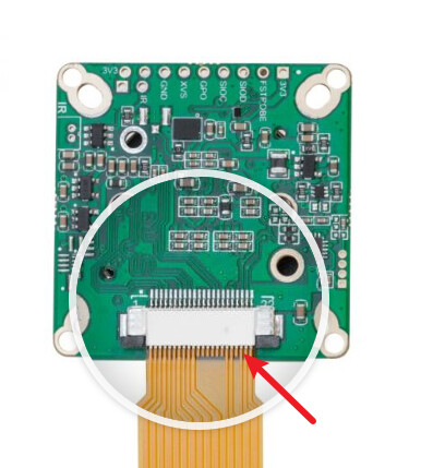
I just bought an IMX477 IR-CUT camera from: Amazon and neither my Pi Zero or Pi 3B+ can see it.
The OS is Bullseye and Glamor has been set active. I have tried both with the camera auto detection on and with it off and using dtoverlay=imx477.
Using journalctl -b I can see the an error IMX477 10-001a: failed to read chip id 477, with error -5. This error appears to be an -EIO error so is too generic to know what the issue is.
i2cdetect -y 10 just shows a bunch of -- values suggesting nothing is being detected.
The overlay appears to be loaded as I can see an entry at /proc/device-tree/soc/i2c0mux/i2c@1/imx477@1a.
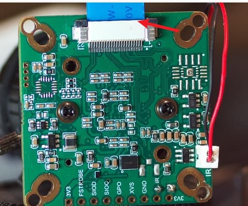
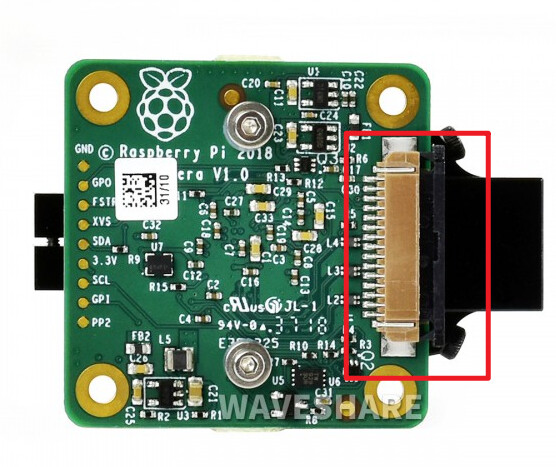
I have tried every cable I have that can connect to the camera and a Pi but nothing works with this new module. My Pi 3B is able to take pictures with another imx477 HQ camera module I have hooked to it but hooking the new IR-CUT module to the Pi 3B results in the same “no cameras available” message in libcamera-hello and in libcamera-vid.
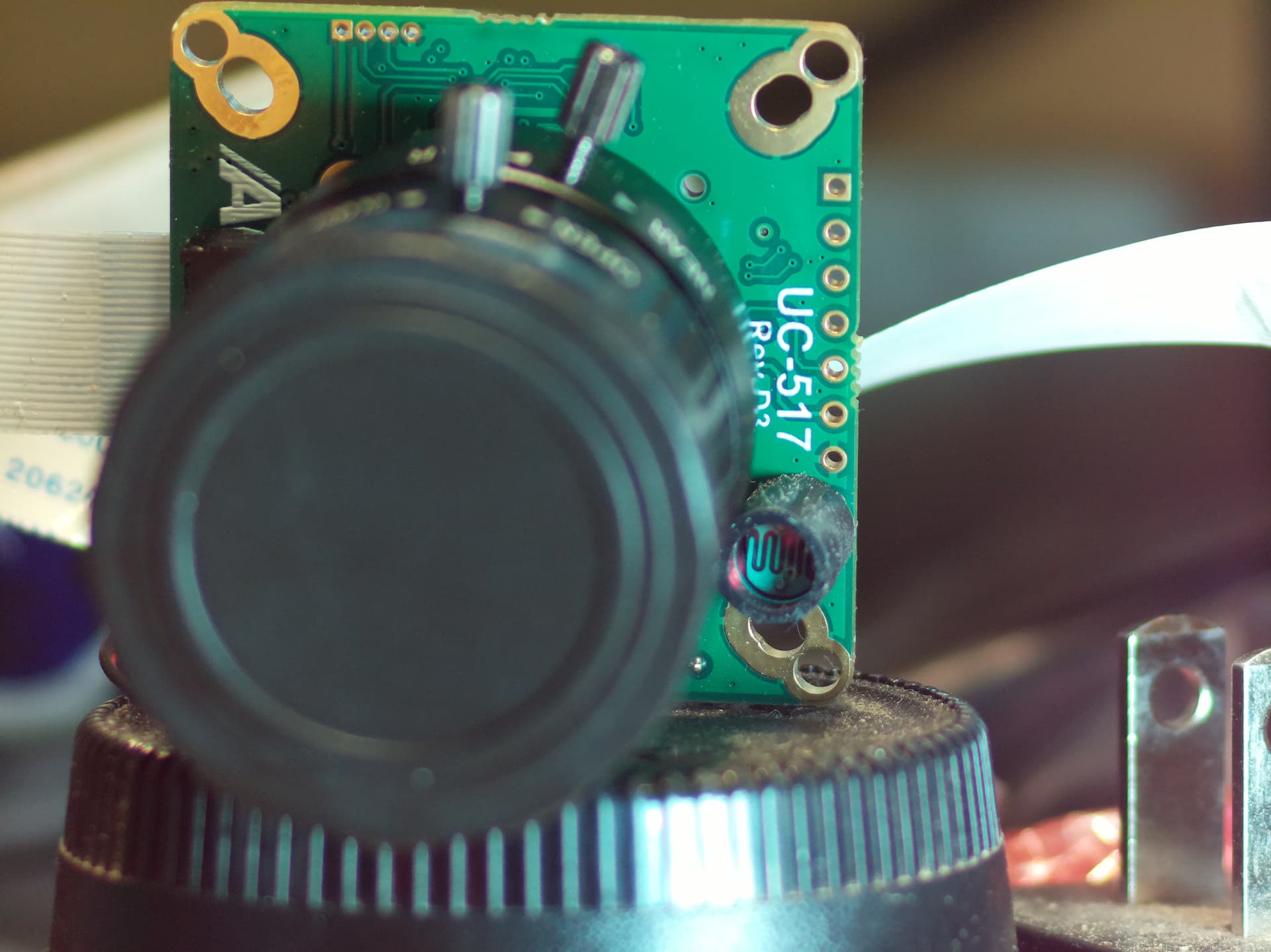
Markings on the new module are “UC-517 Rev.D3”.
At this point I have tried everything I know to try but I can’t even tell if the module powers up or not as there doesn’t seem to be any sort of LED or anything.
Anyone have any ideas on next steps or how to verify if I just have a bad camera module and need to get it replaced?
Thanks for any help.
libcamera-hello output:
$ LIBCAMERA_LOG_LEVELS=*:0 libcamera-hello -t 0 -n
[0:48:38.370990197] [1621] DEBUG IPAModule ipa_module.cpp:334 ipa_rpi_vc4.so: IPA module /usr/lib/arm-linux-gnueabihf/libcamera/ipa_rpi_vc4.so is signed
[0:48:38.373596176] [1621] DEBUG IPAManager ipa_manager.cpp:245 Loaded IPA module '/usr/lib/arm-linux-gnueabihf/libcamera/ipa_rpi_vc4.so'
[0:48:38.379711128] [1621] DEBUG IPAModule ipa_module.cpp:334 ipa_vimc.so: IPA module /usr/lib/arm-linux-gnueabihf/libcamera/ipa_vimc.so is signed
[0:48:38.382236108] [1621] DEBUG IPAManager ipa_manager.cpp:245 Loaded IPA module '/usr/lib/arm-linux-gnueabihf/libcamera/ipa_vimc.so'
[0:48:38.385360083] [1621]  INFO Camera camera_manager.cpp:297 libcamera v0.0.5+83-bde9b04f
[0:48:38.390939039] [1622] DEBUG Camera camera_manager.cpp:69 Starting camera manager
[0:48:38.433415703] [1622] DEBUG DeviceEnumerator device_enumerator.cpp:224 New media device "bcm2835-codec" created from /dev/media3
[0:48:38.435090690] [1622] DEBUG DeviceEnumerator device_enumerator_udev.cpp:96 Defer media device /dev/media3 due to 5 missing dependencies
[0:48:38.451471560] [1622] DEBUG DeviceEnumerator device_enumerator_udev.cpp:322 All dependencies for media device /dev/media3 found
[0:48:38.453621543] [1622] DEBUG DeviceEnumerator device_enumerator.cpp:252 Added device /dev/media3: bcm2835-codec
[0:48:38.459789494] [1622] DEBUG DeviceEnumerator device_enumerator.cpp:224 New media device "bcm2835-isp" created from /dev/media0
[0:48:38.461786478] [1622] DEBUG DeviceEnumerator device_enumerator_udev.cpp:96 Defer media device /dev/media0 due to 4 missing dependencies
[0:48:38.468152428] [1622] DEBUG DeviceEnumerator device_enumerator.cpp:224 New media device "bcm2835-isp" created from /dev/media1
[0:48:38.470377411] [1622] DEBUG DeviceEnumerator device_enumerator_udev.cpp:96 Defer media device /dev/media1 due to 4 missing dependencies
[0:48:38.484840296] [1622] DEBUG DeviceEnumerator device_enumerator_udev.cpp:322 All dependencies for media device /dev/media0 found
[0:48:38.487064279] [1622] DEBUG DeviceEnumerator device_enumerator.cpp:252 Added device /dev/media0: bcm2835-isp
[0:48:38.501389165] [1622] DEBUG DeviceEnumerator device_enumerator_udev.cpp:322 All dependencies for media device /dev/media1 found
[0:48:38.503548148] [1622] DEBUG DeviceEnumerator device_enumerator.cpp:252 Added device /dev/media1: bcm2835-isp
[0:48:38.509460101] [1622] DEBUG DeviceEnumerator device_enumerator.cpp:224 New media device "unicam" created from /dev/media2
[0:48:38.512711076] [1622] DEBUG DeviceEnumerator device_enumerator.cpp:252 Added device /dev/media2: unicam
[0:48:38.517359039] [1622] DEBUG Camera camera_manager.cpp:113 Found registered pipeline handler 'PipelineHandlerVc4'
[0:48:38.527877956] [1622] DEBUG DeviceEnumerator device_enumerator.cpp:312 Successful match for media device "unicam"
[0:48:38.531383928] [1622] DEBUG DeviceEnumerator device_enumerator.cpp:312 Successful match for media device "bcm2835-isp"
[0:48:38.534826901] [1622] DEBUG RPI vc4.cpp:192 Unable to acquire a Unicam instance
[0:48:38.538404872] [1622] DEBUG Camera camera_manager.cpp:113 Found registered pipeline handler 'SimplePipelineHandler'
[0:48:38.542020844] [1622] DEBUG Camera camera_manager.cpp:113 Found registered pipeline handler 'PipelineHandlerUVC'
[0:48:38.544471824] [1622] DEBUG Camera camera_manager.cpp:113 Found registered pipeline handler 'PipelineHandlerVimc'
ERROR: *** no cameras available ***
dmesg output:
$ sudo dmesg | grep imx477
[    0.161807] platform 20801000.csi: Fixed dependency cycle(s) with /soc/i2c0mux/i2c@1/imx477@1a
[   55.774471] imx477 10-001a: failed to read chip id 477, with error -5
[   55.798332] imx477: probe of 10-001a failed with error -5
config.txt contents (this has been changed many times while trying to figure out a solution … this is just the current version of config.txt and it has the same issues reported, above):
$ cat /boot/config.txt
# For more options and information see
# http://rpf.io/configtxt
# Some settings may impact device functionality. See link above for details

#display_rotate=0
#hdmi_cvt=300 300 60 1 0 0 0

# uncomment if you get no picture on HDMI for a default "safe" mode
#hdmi_safe=1

# uncomment the following to adjust overscan. Use positive numbers if console
# goes off screen, and negative if there is too much border
#overscan_left=16
#overscan_right=16
#overscan_top=16
#overscan_bottom=16

# uncomment to force a console size. By default it will be display's size minus
# overscan.
#framebuffer_width=1680
#framebuffer_height=1050

# uncomment if hdmi display is not detected and composite is being output
# hdmi_force_hotplug=1

# uncomment to force a specific HDMI mode (this will force VGA)
# hdmi_group=2
# hdmi_mode=87

# uncomment to force a HDMI mode rather than DVI. This can make audio work in
# DMT (computer monitor) modes
#hdmi_drive=2

# uncomment to increase signal to HDMI, if you have interference, blanking, or
# no display
#config_hdmi_boost=4

# uncomment for composite PAL
#sdtv_mode=2

# uncomment to overclock the arm. 700 MHz is the default.
# arm_freq=800

# Uncomment some or all of these to enable the optional hardware interfaces
#dtparam=i2c_arm=on
#dtparam=i2s=on
#dtparam=spi=off

# Uncomment this to enable infrared communication.
#dtoverlay=gpio-ir,gpio_pin=17
#dtoverlay=gpio-ir-tx,gpio_pin=18

# Additional overlays and parameters are documented /boot/overlays/README

# Enable audio (loads snd_bcm2835)
dtparam=audio=on

# Trying to figure out how to get the IR camera working ...
dtparam=i2c_vc=on

# Automatically load overlays for detected cameras
# camera_auto_detect=1

# Automatically load overlays for detected DSI displays
# display_auto_detect=1

# Enable DRM VC4 V3D driver
# dtoverlay=vc4-kms-v3d
# max_framebuffers=2

# Disable compensation for displays with overscan
disable_overscan=1

[cm4]
# Enable host mode on the 2711 built-in XHCI USB controller.
# This line should be removed if the legacy DWC2 controller is required
# (e.g. for USB device mode) or if USB support is not required.
otg_mode=1

[pi4]
# Run as fast as firmware / board allows
arm_boost=1

[all]
dtoverlay=vc4-kms-v3d
gpu_mem=128
avoid_warnings=2
dtoverlay=imx477
# hdmi_force_hotplug=1
# hdmi_cvt=240 240 60 1 0 0 0
# hdmi_group=2
# hdmi_mode=87
# display_rotate=0