-
Where did you get the camera module(s)?
ArduCam website -
Model number of the product(s)?
SKU: EK004, USB2 shield AR0134 Monochrome CMOS 1.2MP sensor -
What hardware/platform were you working on?
Raspberry Pi Zero 2W -
Instructions you have followed. (link/manual/etc.)
1.2MP AR0134/AR0135 Global Shutter - Arducam -
Problems you were having?
When sending power through RP0, 22 pin adapter to USB2 shield AR0134 combo, RP0 shuts off and the shield does not seem to register any connection. Have tried both 5.0v 2.5amps and 3.3v -
The dmesg log from your hardware?
nothing -
Troubleshooting attempts you’ve made?
Tested various processors (two RP0 2W’s and RP0 v1.3)
Tested diff 22pin cables
they both function separately -
What help do you need?
We are fairly new to the arducam/processor community. We have tested imaging capabilities on the AR0134 and it is functioning properly. We have also tested sample images on RP0. We are concerned that the AR0134 is simply not compatible with the RP0 2W…? There is little documentation of physical initial setup/handling. Also, are there any specific steps that we need to config AR0134 for proper communication between RP0 and cam?
The USB2 shield is connected to the host through USB, there should be no incompatibility, how did you connect it? Can you provide a photo?
Can you not connect the shield via 22-22pin cable through P1?
I don’t understand very well, why do you need 22-22pin cable to connect raspberry pi?
The USB2 shield should use the USB port. The AR0134 also cannot be directly connected to the Raspberry Pi it is a DVP interface.
That was just our understanding of how to connect the two. We did not want to draw as much power through using the microusb port. There is a 22pin camera interface on the raspberry pi zero and we assumed that the 22pin interface on the usb2 shield was how we could connect the two and power the shield/img sensor.
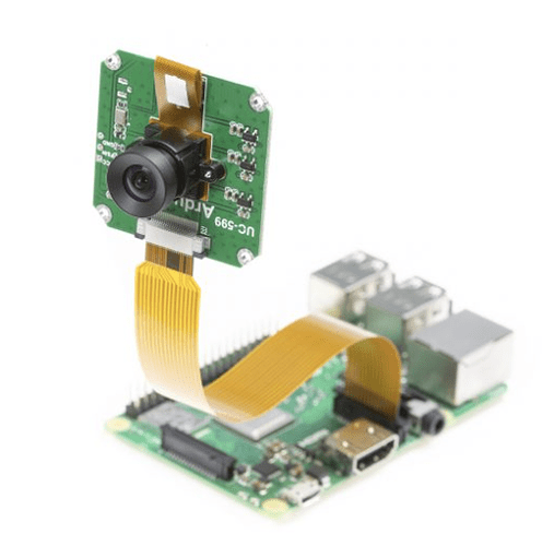
We may have been misled with how other configs are in pictures…? I am unsure. Here is an example picture I am referencing.
So if we cannot power the shield/AR0134 through the 22pinout on the USB2, then what is the 22pinout (I believe is P1) used for?
The interface on Pi1 is CSI/MIPI interface, while AR1034 is DVP interface, they are not compatible.
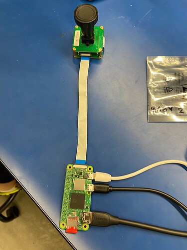
The USB2 shield is already attached to the AR0134 through the 30pin connection. I am talking about getting the raspberry pi connected to the USB2 shield. Sorry, it took me until today to get pictures, but this is our set up. the long cable is the 22pin connection.
If that connection is just not compatible, that’s all I need to know! Thank you for your patience.
Yes, they are not compatible, the 22pin on the USB2 Shield is for MIPI receiver, it cannot be used to connect another receiver (but it can be connected to a MIPI camera)

