I want to have multiple (2-4) cameras synced for 3D position estimation detecting Fiducial markers.
The camera system will be estimating the tool pose of a 6DOF robot, likely mounted to the end of arm.
This is desired while the arm is moving and preferably have time-stamping option to sync with an IMU.
I was looking at using the USB3.0 Shield Plus to capture images from 2 OV2311 or OV9281 sensors.
The definition of the USB3.0+ says that the “two cameras cannot be used at the same time” but also that they can be used to achieve “dual-lane synthesis”/“Double column resolution”, which is a bit confusing to me.
Am I right to understand that 2 MIPI cameras can be used (synced) simultaneously but not DVP?
I am on a tight budget, so multiple USB3.0+ shields can’t be purchased easily. But if I wanted 4 cameras or more, what’s my options?
Can I for example use the one 3.0+ shield for timestamping, and sync an external trigger with multiple UVC cameras?
I read that a stereo camera/multicam hat could be connected to the USB3+ shield? Is there an option for multiple different direction cameras, like the multicam hat, without a Raspberry Pi?
Am I right to understand that 2 MIPI cameras can be used (synced) simultaneously but not DVP?
Yes, USB3.0 Plus has two MIPI ports. It can combine two identical cameras into one image output (fully synchronized), but it requires a modified camera.
I am on a tight budget, so multiple USB3.0+ shields can’t be purchased easily. But if I wanted 4 cameras or more, what’s my options?
Maybe you can use USB3.0 Plus and 1MP*4 Quadrascopic Monochrome Camera Bundle Kit, but please note that it does not support automatic exposure, and the exposure of the four cameras can only be set to the same value. (And need a special version)
Can I for example use the one 3.0+ shield for timestamping, and sync an external trigger with multiple UVC cameras?
In theory, it is feasible, but you need to pay attention to whether your UVC camera supports external trigger.
I read that a stereo camera/multicam hat could be connected to the USB3+ shield? Is there an option for multiple different direction cameras, like the multicam hat, without a Raspberry Pi?
What do you mean by combining the two images into one image output?
Is it 1 image with two layers? Or something different?
Yea, with the UVC Cameras I was looking at the 2 models with support (OV9281 and OV2311).
Would the USB3+ Shield have a connection point I could directly wire to the UVC Cameras as a source of the external trigger or would an Arduino still be needed to send the pulse?
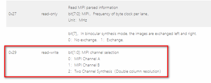
The pictures of two cameras are combined into one picture, side by side.
For example, the image of one camera is 640x480 and the two combined is 1280x480.
USB3.0 doesn’t care what the trigger source is, it only needs to meet the pulse requirements for camera triggering.
I mean, can the USB3.0+ Shield be the trigger source?
For instance is there a pin on the usb shield that can send the trigger pulse to the other cameras, when the 3.0+ shield captures an image normally?
I have purchased a USB3 Plus shield and 2 OV2311 sensors.
They are both connected through the MIPI connections.
I’m struggling to find how to configure the board to receive both images side-by-side.
We already have a similar configuration, but it requires a special camera module (able to transmit the clock signal through the FFC cable).
The normal release version does not have this feature.
I did request that the camera sensors be modified when I purchased the devices through the website that Arducam.com linked me to (Uctronics).
As well as communicated it multiple times in email that I needed the bundle to perform dual-lane synthesis.
How can I verify whether this happened?
Otherwise, how would I get my hands on the special camera module? If not through the Arducam website?
Not sure which two versions you are talking about?
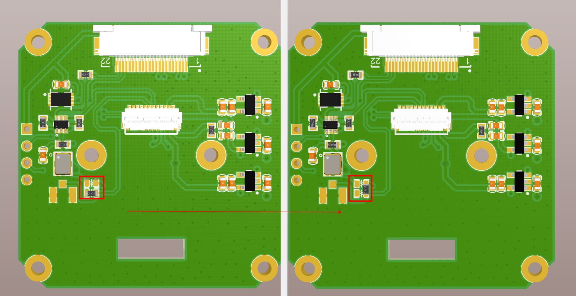
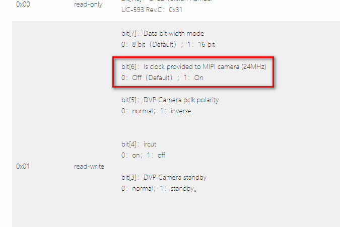
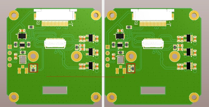
After modifying the resistor, the clock signal needs to be provided from the FFC. If the clock is not provided from the FFC, the camera cannot be used (for example, it is used on other platforms)
I was asking if the resistor seen in the left image is the same as the one in a different position in the right image.
I see, so it will be usable on the USB 3.0 Shield Plus (with register set to send clock signal)
But would no longer be usable on a Raspberry Pi for instance?