1.Which seller did you purchase the product(s) from?
2.The Model number of the product(s) you have purchased?
USB2 Rev E Shield
3.Which Platform are you using the product(s) on?
4.Which instruction are you following?
5.Has your product ever worked properly?
6.What problems are you experiencing?
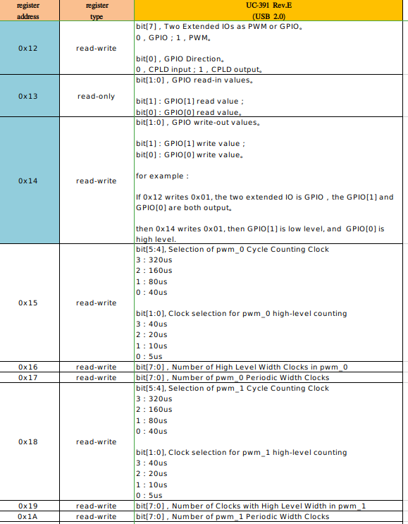
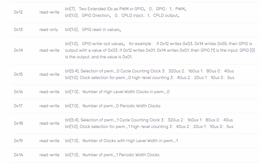
I see 2 GPIO pins mentioned in the register table for the USB2 Rev E Shield.
Are these pins available on the PCB? I do not see them in the connector pin outs.
I do see pin header holes next to the USB connector, maybe these are the GPIO?
7.What attempts at troubleshooting have you already made?
I can control the 2 GPIO pins as outputs but I can not read them as inputs.
The setting of 0x12 works correctly, I can set the pins set correctly as both Outputs and Inputs.
The setting of 0x14 works correctly when the pins are set as Outputs.
u8Buf[0]=0x03;
ArduCam_setboardConfig(tempHandle, 0xD7, 0x4600, 0x1200, 1, u8Buf);
u8Buf[0]=0x00;
ArduCam_setboardConfig(tempHandle, 0xD7, 0x4600, 0x1400, 1, u8Buf);
Pins measure Low.
u8Buf[0]=0x03;
ArduCam_setboardConfig(tempHandle, 0xD7, 0x4600, 0x1400, 1, u8Buf);
Pins measure High.
Now setting the pins as inputs. And reading 0x14 to get the input pin values.
u8Buf[0]=0x00;
ArduCam_setboardConfig(tempHandle, 0xD7, 0x4600, 0x1200, 1, u8Buf);
ArduCam_getboardConfig(tempHandle, 0xD7, 0x4600, 0x1300, 1, u8Buf);
printf(“GPIO Inputs 0x%x\n”,u8Buf[0]);
The read of 0x13 does not return the correct value as the input pins are toggled Low and High.
0xD7 in ArduCam_getboardConfig/ArduCam_setboardConfig represents of write.
I suggest you use ArduCam_writeReg_8_8, ArduCam_readReg_8_8
E.g:
ArduCam_writeReg_8_8(tempHandle, 0x46, 0x12, 0x00)
uint32_t value;
ArduCam_readReg_8_8(tempHandle, 0x46, 0x13, &value);
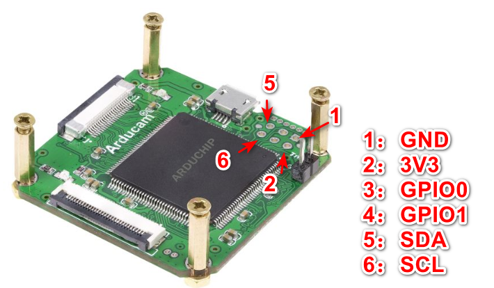
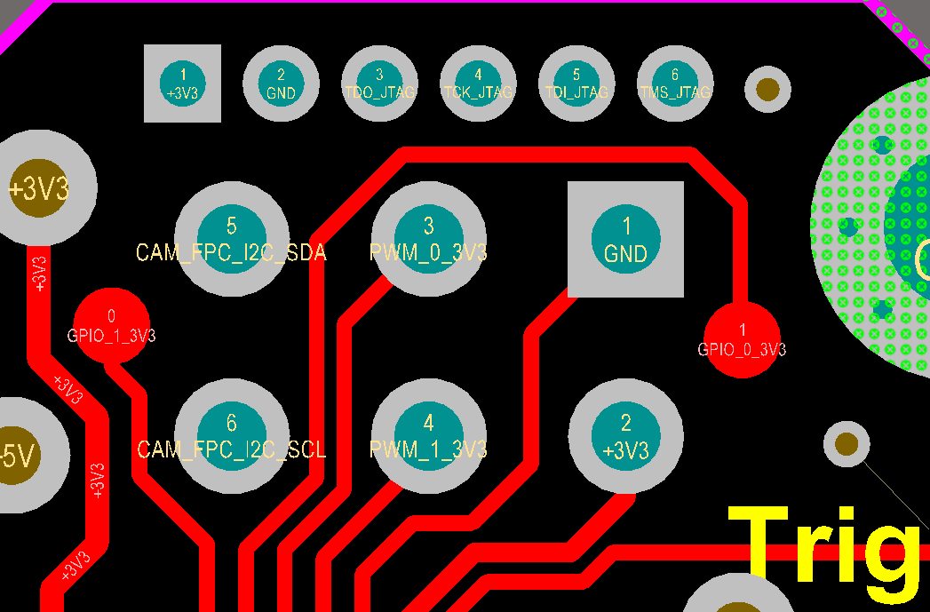
 Note: These pins do not have headers at the factory, you need to solder them yourself.