Hey
Can you please specify the optical specs regarding the Arducam 2MP Global Shutter OV2311 Monochrome module? (The Focal length, F# and ect)
Thanks
Hey
Can you please specify the optical specs regarding the Arducam 2MP Global Shutter OV2311 Monochrome module? (The Focal length, F# and ect)
Thanks
Hi,
Sorry for replying you so late. At present, we don’t have optical specs about ov2311 also.
Thanks
I’m trying to get 10bit output out of this camera - RAW by using your USB3 and MIPI adapter. But when I choose 10bit, I get an error. Could you help me with this please?
Hi, we have raw10 configuration on USB3.0. Please refer to our cfg here:
Hey,
I’ve tried the “OV2311_MIPI_2Lane_RAW10_8b_1600x1300_60fps” file, via the python code provided, and the pixel have 0-255 values. Is there some configuration missing?
I have tried to change the

And I get an error though the parameters are OK (I have tried with BIT_WIDTH=10 too)
{‘u32CameraType’: 0, ‘u32Width’: 1600, ‘u32Height’: 1300, ‘usbType’: 0, ‘u8PixelBytes’: 2, ‘u16Vid’: 0, ‘u32Size’: 0, ‘u8PixelBits’: 16, ‘u32I2cAddr’: 192, ‘emI2cMode’: 2, ‘emImageFmtMode’: 0, ‘u32TransLvl’: 0}
Serial: AU3S-2003-0001
Capture began, rtn_val = 0
Error capture image, rtn_val = 65316
When I run it with BIT_WIDTH=10 as stated in RAW10 file, I get 255 as the biggest number. It happens with all the modules I’ve got. Could you please advise?
Thanks
The error code 65312 (FF24) data length error, which means the expected data size defined in the config file doesn’t match with the incoming data size.
You can not simple change the BIT_WIDTH alone. it should match with the sensor configuration and the MIPI adapter board settings, it is complex.
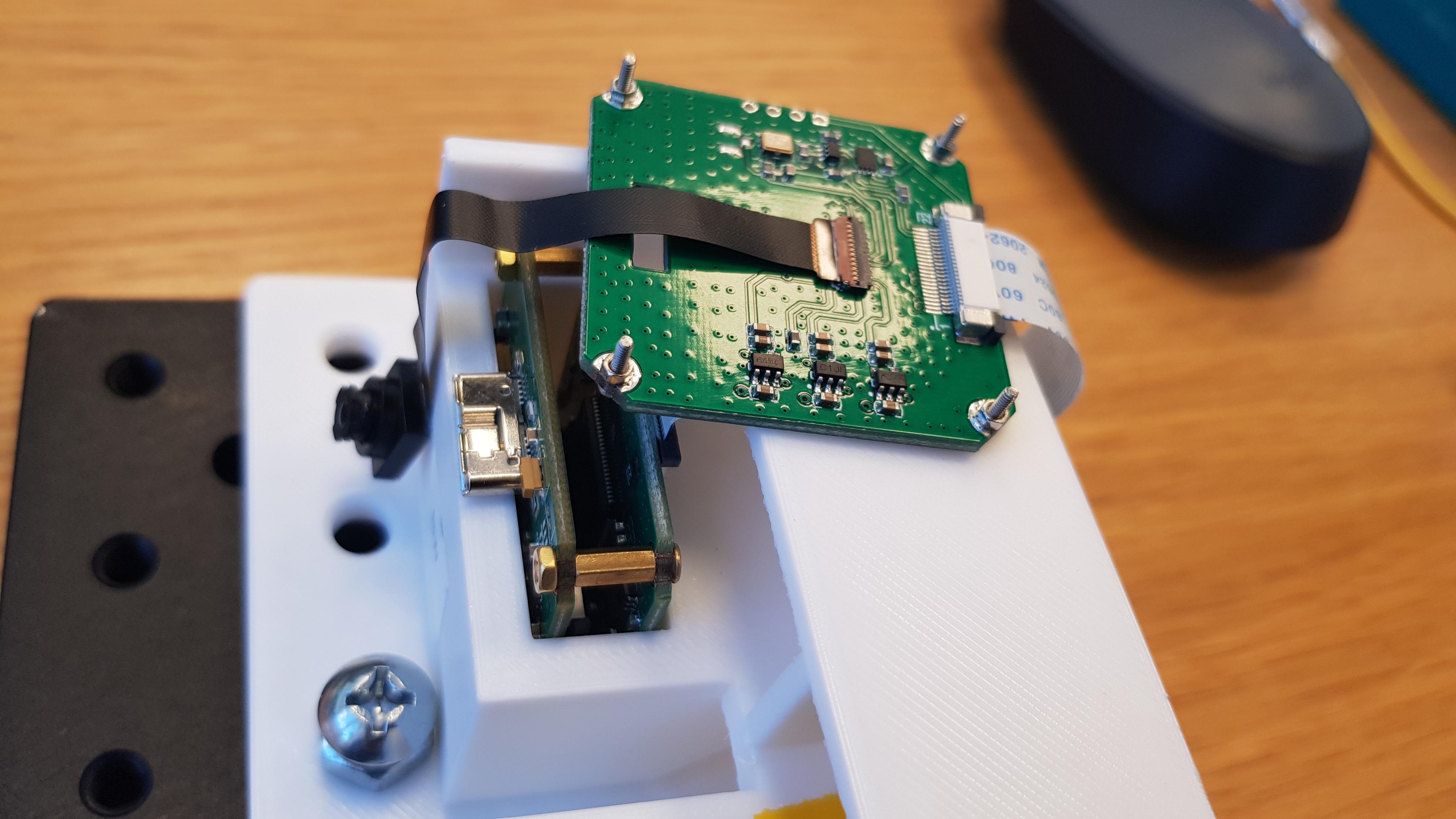
Can you show me your hardware setup photo? So that we can suggest which config is correct for RAW10 mode.
Regards
Lee
Sure,
That’s the setup. It also runs an error with the GUI provided - when I chose the “10bit” option
The setup is pretty simple, the USB3.0 Shield → MIPI adapter–> OV2311 Sensor board–> OV2311 sensor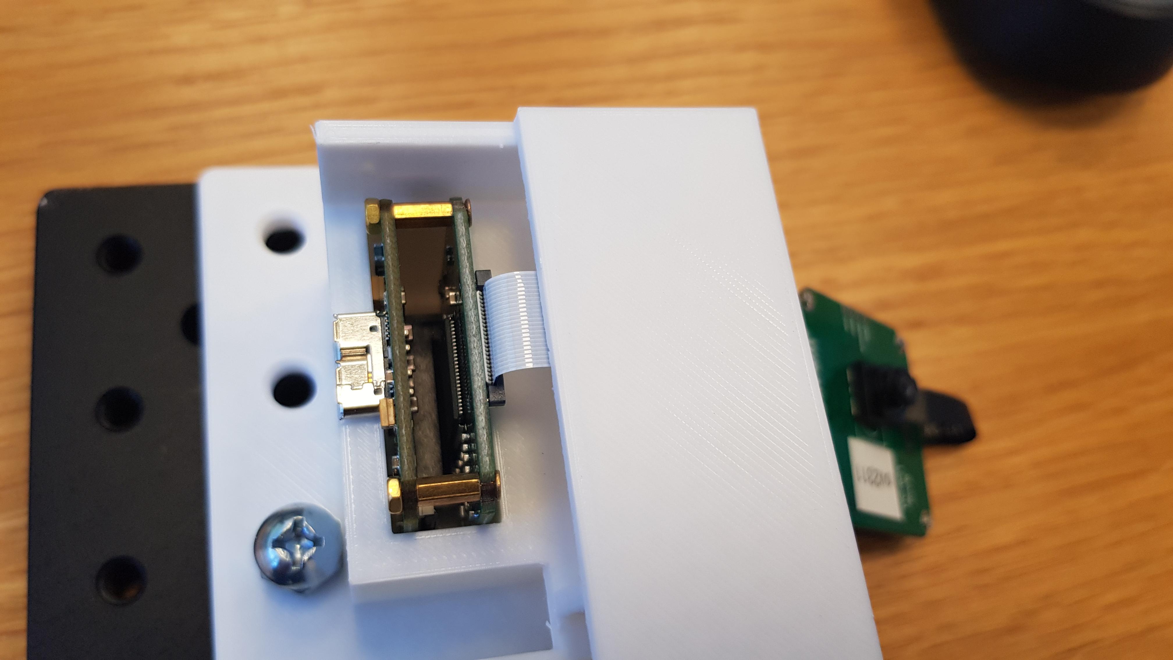
Thanks
Yokhai
This MIPI adapter board currently only supports 8bit mode.
RAW10 can be decoded, but only for transparency transfer to the SDK.
We have to update the SDK to support RAW10.
So please use RAW8 at this moment.
Sorry for the inconvenience.
Lee
Thanks for the reply.
This is true for all cameras I use. Is it solvable with the USB2.0 shield?
I really need the 10-bit compatibility. Is there some way you could help with that?
we will try the 10bit mode here, and I guess the GUI now can’t render the correct image, but we can get RAW image file, and write additional parsing code to get the correct image.
Will let you know soon.
Yokhai
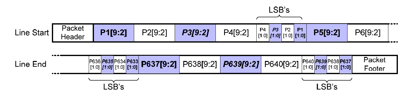
We have composed a new configuration file for OV2311 RAW10 output. The data packing style is bellow, the 2-bit LSB[1:0] of each 4 pixels are after consecutive 4 pixel data. So the configuration file define the row size is 2000 which is calculated from 1600x(10/8). You have to save the RAW file and render correct image by yourself.
Thanks I’ll try it out and let you know.
Will this kind of configuration work for the OV9281/OV7251?
Thanks
This config file is only for OV2311, for other cameras we have to compose other config files.
Thanks
It seems that it works when I parse the data.
Could you please tell me what modification needed for the OV7251 and the OV9281?
Hi,
Great to hear you can parse the data. Would you like to share your code here?
Please refer to the 7251 and 9281 raw10 config
Hey,
Thanks - I’ll check it out.
Currently, I have implemented it in MATLAB, it is not efficient, but works - for POC - it is acually the algorithm for parsing. After implementing in python - I’ll share the code.
fin=fopen(‘image0.raw’,‘r’);
I=fread(fin,2000*1300,‘uint8=>uint8’);
Z=reshape(I,2000,1300);
Z=Z’;
Z_MSB = Z;
Z_MSB(:,5:5:end) = [];
Z_LSB_raw = Z(:,5:5:end);
Z_LSB = zeros(size(Z_MSB));
for i=1:1300
for j=1:4:1600
val = Z_LSB_raw(i,(j-1)/4+1);
bin_num = dec2bin(val);
while (length(bin_num)<8)
bin_num = [‘0’ bin_num];
end
Z_LSB(i,j) = bin2dec(bin_num(7:8));
Z_LSB(i,j+1)= bin2dec(bin_num(5:6));
Z_LSB(i,j+2)= bin2dec(bin_num(3:4));
Z_LSB(i,j+3)= bin2dec(bin_num(1:2));
%i
end
end
Z_RAW10 = double(Z_MSB)*4+Z_LSB;
Hey
I checked that . You have a little mistake there for it to work. Currently the size is 640480 , and needs to be 800480 (as you suggested above)
CFG_MODE = 0 TYPE = OV7251 SIZE = 800, 480 BIT_WIDTH = 8 FORMAT = 4, 0 I2C_MODE = 2 I2C_ADDR = 0xC0
Hi,
Thanks for your script. For the 7251 sensors, the original size is 640x480.
It can’t be configured too bigger.