@GuillaumeLeclerc
Hi, Thanks for your detail message.
Yes, you are right, the data you send is not the jpeg header. Many factor will cause this phenomenon.
Such as the long cable line and unstable hardware connection etc.
Have you tested the demo we released? We should have tested the demo we released. in order to split the issue, my suggestion is please use a shorter cable line and our demo to test it firstly to make sure the hardware is normal, Then let’s check the issue step by step.
Feel free to let me know if you need more help.
Bin from Arducam support team.
The cables are very short (<10cm) and when I keep the 320px default resolution I get a correct JPEG header every single time so I’m extremely confident that there are no issues there.
If you look carefully at my script you would see that the functions I’m calling are the ones from your Pico repository. The only difference is that I’m not taking the commands from the computer because the Camera Host app that you ship in the RPI Pico repository doesn’t work. I get “Failed to execute script camera2” Every time I try to run it. (And also I need to be able to run the camera without it being plugged to a computer obviously, otherwise I would have bought a USB camera…)
I ported your Arduino library to PICO boards and I managed to get an image so my wiring has to be correct. There is clearly a problem with your CircuitPython library
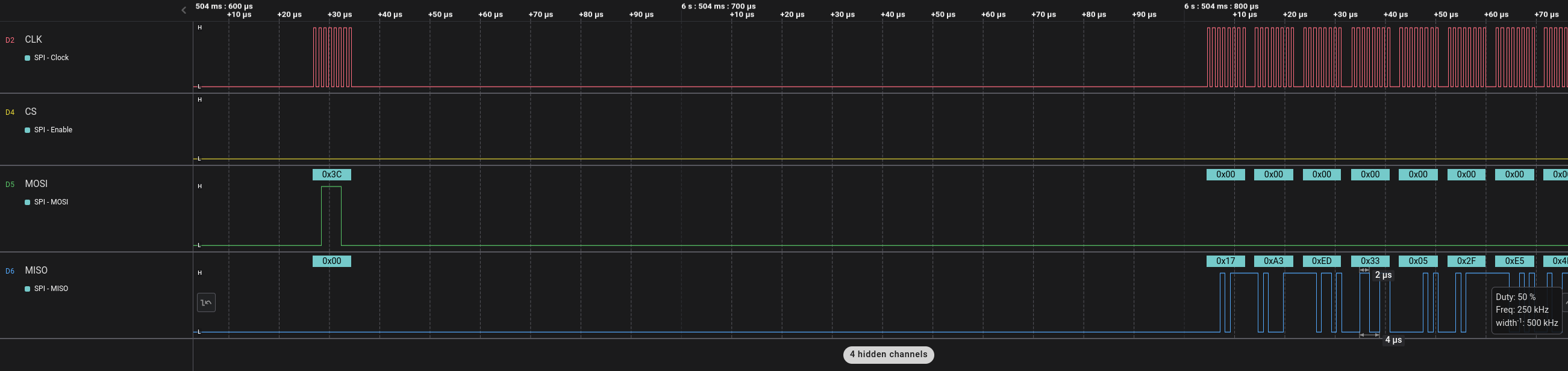
To convince you that this is not a problem with the wires here is a screenshot of the result of a logic analyzer. We see me writing the 0x3C byte to start the burst mode and we see that the values of the first bytes are not JPEG signatures
I’ve spend ludicrous amount of time troubleshooting I hope you could give me some insights here. In the end what I ended up doing was to use a multichannel oscilloscope and track all signals and compare the two drivers (The Arduino one that works and the circuit python that doesn’t)
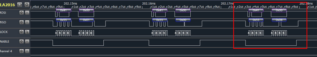
After interpreting the signals I decoded the SPI protocol and compared the two drivers side by side. See the diff below: Arduino is Left and Python is right.
Above this we have the 0x41 calls which check if the image is ready (this repeats for a while)
At line 500 for both driver the image becomes available
From there the size of the image is read with with reads at address 0x42, 0x43 and 0x44
Line 515 the command to read in burst (0x3C) is then written on the bus and we should start receiving the image
On the left (The arduino version) we see the 0xFFD8FF denoting a JPEG image, but on the right we see 0x3FEFB2 instead
Something I’m wondering is why the Arducam would answer 0x08 to the 0x41 command on Arduino when the image is ready but 0x9 for the Python version (line 500).
I would really appreciate some help here, we are developing a product that would need hundreds of these camera module so getting them to work is really important to us.
@GuillaumeLeclerc
Thanks for your detail check information. Your diagnosis is very professional. In fact, After start capture, we loop read the 0x41 address until the value in the address is 0x08 which means one frame is over.
We just need to care about bit[3]. Don’t worry and we will test it and reply you as soon as possible.
Other than this the I2C protocol is bit identical.
I know only bit[3] is relevant here but this is literally the only thing that differ between the two drivers other than the size of the image and the content of the image itself so I thought it might a clue at what is going on and wanted to tell you about it.
Since the data on the buses seem to match maybe it’s a timing problem. Are there restrictions anywhere : some delays that are crucial or maybe things that need to happen really fast ?
If that can be of any help I have the Capture files in the .sal format for both drivers. I wanted to upload them here but the forum only accepts images.
I found the issue. The python version doesn’t have the delay(1) in wrSensorReg16_8 but the Arduino has. After adding it it works now! I suggest you update the code and test your python driver more thoroughly.
@GuillaumeLeclerc
I am not sure about the speed of the micropython and CircuitPython. But I think it is necessary to add delay between the i2c write in order to make sure the sensor init is normal.