I am attempting to connect the Arducam Mini 2MP Plus to the nRF52840-DK embedded board via the SPIM interface, utilizing bare metal programming. According to the Arducam datasheet,
The ArduCAM SPI slave interface is fixed SPI mode 0 with POL = 0 and PHA = 1. The
maximum speed of SCLK is designed for 8MHz, care should taken do not over clock the
maximum 8MHz. The SPI protocol is designed with a command phase with variable data phase.
The chip select signal should always keep asserted during the SPI read or write bus cycle.
The first bit[7] of the command phase is read/write byte,
‘0’ is for read and ‘1’ is for write,and the bit[6:0] is the address to be read or write in the data phaseSPI Bus Write Timing
The SPI bus write timing composed of a command phase and a data phase during the
assertion of the chip select signal CSn. The first 8 bits is command byte which is decoded as a
register address, and the second 8 bits is data byte to be written to the ArduChip internal registers.
SPI Bus Single Read Timing
The SPI bus single read timing is for read operation of ArduChip internal registers and single
FIFO read function. It is composed of a command phase and a data phase during the assertion of
chip select signal CSn. The first 8 bits is command byte which is decoded as a register address, the
second 8 bits is dummy byte written to the SPI bus MOSI signal, and the content read back from
register is appeared on the SPI bus MISO signal.
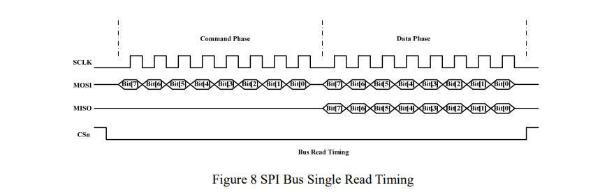
The location of test register is Test register is 0x00.
I have written this code to test the SPI connection. According to the diagrams, the clock is active high and the data is read on the leading edge of the clock. The datasheet states that the POL and PHA macros should be set to 0 and 1 respectively, which I have done. I am sending a value to the test register and attempting to read the same value back, but instead of 0x55, I am receiving other values (0x52, 0x1c).
#include<stdint.h>
#include “nrf52840.h”
#include “nrf52840_bitfields.h”
#include “nrf_delay.h”
#include “nrf_gpio.h”int spi_init(unsigned int pin_cs, unsigned int pin_mosi, unsigned int pin_miso,unsigned int pin_clk)
{
NRF_SPIM3->PSEL.CSN = pin_cs;
NRF_SPIM3->PSEL.SCK = pin_clk;
NRF_SPIM3->PSEL.MOSI = pin_mosi;
NRF_SPIM3->PSEL.MISO = pin_miso;/* Change the SPI mode here */ NRF_SPIM3->CONFIG = (SPIM_CONFIG_CPHA_Leading << SPIM_CONFIG_CPHA_Pos) | (SPIM_CONFIG_CPOL_ActiveHigh << SPIM_CONFIG_CPOL_Pos) | (SPIM_CONFIG_ORDER_MsbFirst << SPIM_CONFIG_ORDER_Pos); /* Change the frequency here */ NRF_SPIM3->FREQUENCY = SPIM_FREQUENCY_FREQUENCY_M4; NRF_SPIM3->ENABLE = (SPIM_ENABLE_ENABLE_Enabled << SPIM_ENABLE_ENABLE_Pos); return 0;}
int spi_read(uint8_t address)
{
uint8_t tx_buf[2];
tx_buf[0] = address;
tx_buf[1] = 0; // dummy byteuint8_t rx_buf[2] ; rx_buf[0] = 0; rx_buf[1] = 0; // dummy byte /* The SPI transaction will last for max(n_tx, n_rx) bytes */ NRF_SPIM3->TXD.MAXCNT = 2; NRF_SPIM3->RXD.MAXCNT = 2; NRF_SPIM3->TXD.PTR = (uint32_t)tx_buf; NRF_SPIM3->RXD.PTR = (uint32_t)rx_buf; NRF_SPIM3->EVENTS_END = 0; /* Start the transaction */ NRF_SPIM3->TASKS_START = 1; /* Busy wait until it has finished */ while (NRF_SPIM3->EVENTS_END == 0) { }; NRF_SPIM3->EVENTS_END = 0; return rx_buf[1];}
int spi_write(uint8_t address, uint8_t value)
{static uint8_t tx_buf[2]; tx_buf[0] = address; tx_buf[1] = value; /* The SPI transaction will last for max(n_tx, n_rx) bytes */ NRF_SPIM3->TXD.MAXCNT = 2; NRF_SPIM3->RXD.MAXCNT = 0; NRF_SPIM3->TXD.PTR = (uint32_t)tx_buf; NRF_SPIM3->RXD.PTR = (uint32_t)0; NRF_SPIM3->EVENTS_END = 0; /* Start the transaction */ NRF_SPIM3->TASKS_START = 1; /* Busy wait until it has finished */ while (NRF_SPIM3->EVENTS_END == 0) { }; NRF_SPIM3->EVENTS_END = 0; return 0;}
int main(void)
{
spi_init(31, 30, 29, 28);
int data = 0xff;
while(1){
// spi_testing
spi_write(0x00 | 0x80,0x55);
data = spi_read(0x00 & 0x7F);
if(data == 0x55){
// SPIM is working
}
nrf_delay_ms(1000);
}
}
I have tested the functionality of the spim interface on the nrf52840-dk board using a Logic analyser, and the board appears to be working correctly. Is there something I am missing or doing wrong?